|
W A T K I N S W 2 5 |
|
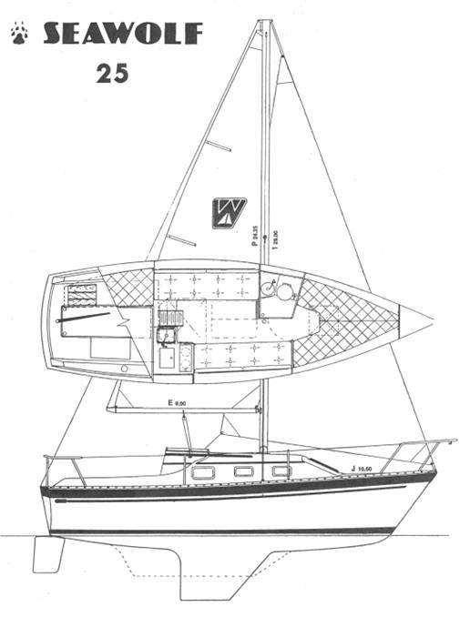
D E S I G N & H I S T O R Y The W25 was first introduced in 1983 and production continued until 1989 with at least 132 boats built. The fully encapsulated keel came in two variations, a shoal draft of 30” and a deep draft of 4’. The deep draft version is very rare. The bow configuration also had two variations, with and without anchor platform. The forestay was shortened slightly to accommodate the thickness of the wood platform but its location was not changed, thus the sail plan is the same for both versions. The anchor platform version used a different bow pulpit which stuck out and surrounded the anchor platform. |
|
SPECIFICATIONS
LOA…………..........…..224’11” DWL…………..........…….21’0” Beam…………..........……..8’0” Draft………...…...........2’6”/4’0’ Displacement….......4,800 lbs. Ballast……...........….1,900 lbs. Sail Area……...........265 sq. ft. Mast Height Above DWL.32’9” Headroom………………...5’11” Berths……………..…….…..5/6 Water Capacity….……..40 Gal Engine: Outboard ...7.5-15 HP Engine: Inboard… .9 HP Diesel
|
|
Other variations include the optional diesel engine, wheel steering, wood strips on the cabin sides, pen rails on the cupboards, flush toilet, hot water and pressurized water to name a few. The boats were custom built to order so each boat had unique features requested by it’s future owner. Other common options were the folding counter top extension on the forward end of the counter and fiddles around the counter tops. The style and location of the dish rack changed from boat to boat. Spars and rigging were originally made by Kenyon and by 1986 had changed to Isomat (both no longer in business but parts are available). Another variations is boats up through 1986 with Yanmar Diesels had the prop shaft exit high in the hull and extended about a foot in the open to a metal support strut. These models cannot use a folding prop because the prop is only 4’ from the rudder. Late models have the engine set about 4” lower in the hull. The prop shaft exits a shaft log with over a foot of space between the propeller and the rudder. Early boats had two opening plastic ports made by Gray (Now Pompanette) per side. Later boats had three opening extruded aluminum ports per side. All six ports have screens.
Factory brochures and rigging data are available for download in PDF format. The rigging data is for an Isomat spar and will be slightly different for the Kenyon spar.
H U L L & D E C KThe hull is molded as a single unit of a combination of polyester resin and fiberglass woven roving and multidirectional chopped strand fiber (MCSF). The keel is molded integrally with the hull and all ballast is contained inside. The deck and cockpit, like the hull, are molded as a single unit of a combination of polyester resin and fiberglass woven roving and MCSF. Plywood coring is incorporated between layers of fiberglass in the cabin top, deck, seat, and cockpit sole areas to give additional stiffness. The non-skid finish is molded into the deck. The exterior finish is pigmented gelcoat molded onto the fiberglass. The boot and sheer stripe are also gelcoat molded permanently into the hull. R U D D E R & S T E E R I N GThe rudder is molded as a single piece of solid high density foam with a protective skin of fiberglass and a gelcoat finish. The rudder post, molded integrally with the rudder, is solid stainless steel, which is welded to a steel blade in the interior of the rudder. The rudder post is mounted in the hull and supported in a plastic tube which extends all the way to the top of the combings unless it is shortened to accommodate a quadrant for pedestal steering. Thus no stuffing box is needed unless wheel steering is installed. S P A R S & R I G G I N GAll spars (mast, boom, and spreaders) are extruded aluminum 6061-T6 alloy, with a protective coating an all external surfaces. The masts has a single spreader, and booms with single reefing. Production started with Kenyon spars and by 1986 models had changed to Isomat. The standing rigging is made of stainless steel wire. The forestay attaches to the stem head fitting at the bow. This is fabricated of welded stainless steel plates and through bolted to the hull. All other stays and shrouds are attached to chainplates at the edge of the deck and are through bolted to the hull. Additional fiberglass reinforcement is molded into the hull in all chainplate areas. See the “Download” section for a downloadable file with rigging details. The main sheet blocks are mounted on either side of the cabin top and a continuous line ran between cabin top blocks and boom double sheaves. This is a workable arrangement but makes it difficult to bring the boom near the center for close hauled point of sail. Several owners have changed this to either dual sets of mainsheet blocks, one on either side or a traveler system to aid in upwind pointing ability. The dual block arrangement allows for better control but requires that the main sheet be tacked like a jib on each tack. The traveler can block the view on an already tall cabin top, so each system has it proponents and detractors. I N T E R I O RThe interior is a molded fiberglass unit with bulkheads and cabinetry fastened to it with screws, bolts, and adhesives. The interior molded assembly is bonded to the hull with woven roving and mat, that when completed, forms a single unit structure having great strength and rigidity. A U X I L A R YMany boats were equipped with outboards supplied by the owners. Outboard locations vary from either side to centered. The optional boarding ladder was then position to suite. Yanmar diesel engines were optional equipment. If the inboard option was chosen, a Yanmar 1GM10 was fitted. As mentioned in the first paragraph, the engine mounting and propeller shaft were modified slightly some time after 1986 to lower the engine in the hull and make the installation more consistent with the other Watkins models. The propeller shaft is made of 1" stainless steel and exits the hull through a stuffing box. It is supported at the inboard, or engine end, by the shaft coupling, and at the aft end by a cutless bearing in a shaft log that is a continuation of the keel. In Yanmar engines, the water pump draws water through the engine intake port, circulates it through the engine block, and then into the muffler. The water is mixed with the exhaust gases in the engine mixing elbow and discharged overboard through the exhaust port. E L E C T R I C A L . .S Y S T E MThe standard battery configuration consisted of one 12-volt battery. However most owners opted for a second battery. When both batteries are mounted on the battery shelf in the starboard cockpit locker, the boat tends to list to starboard. To remedy this many owners have moved the second or even both batteries to other locations. The most common optional location is in the locker under the port settee. Another possible location is under the quarter berth. Most dual battery systems have a master switch to allow the batteries to be connected in parallel to allow single or combined use and charged from the shore power or the motor generator. Wiring was stranded untinned wire with unsoldered crimp connections. This holds up well on fresh water boats but eventually will need replaced with marine grade tinned wiring on boats exposed to salt water. |